Before >
 < After
Our T4 build 2004-5
Two Batteries under the Bonnet of
a T4 Camper
Before >
< After
To maximise the available space within the body of a camper conversion it is possible to mount two batteries in the area of the original T4 battery. The auxiliary battery is limited in size and therefore capacity but if you can work within these constraints the job is quite feasible.
The following descriptions are as correct and complete as possible neither myself or Volkswagen Owners Club Great Britain can be responsible for errors or misinterpretations of these details and any damage that may be caused. Please read through all information here and asses what cable and connectors you will need before starting work.
Tools required.
Medium flat
screwdriver. -
Cross-head screwdriver. -
8mm spanner. -
10mm spanners open ended and socket. -
13mm spanners open ended and socket.
Crimping tool capable of crimping connectors for up to 10 sq. mm cable. -
Hacksaw. -
Flat File. -
Work bench with vice. -
A medium sized soldering iron is useful but not essential.
The Conversion.
To achieve the conversion it is necessary to rotate the existing battery by 90 degrees moving the –ve terminal to the rear under the edge of the fresh air intake and sliding it towards the engine. The existing battery support plate is much too short in the front to back dimension but is wide enough to fit another battery under the edge of the front wing.
For details of the additional support plate see diagram (.pdf file downloadable here) . This plate is made of substantial steel, in my case stainless as I have a friendly stainless steel fabricator. The strength is necessary as support is provided in a cantilever fashion from the original mounting. [Picture of complete plate]
Early vehicles that have no other objects intruding into the required space between the battery and back of headlight, just a lack of support for the batteries. Simply fitting the new mounting plate and necessary clamping rod the job is mechanically almost complete.
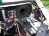
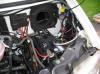
However on later vehicles with a fuse box and engine ECU located in front of the existing battery there are a few modifications to tackle [Picture]. This does take a while and some thought.
This work should not be attempted by anyone who does not feel confident in carrying out some basic electrical modifications to the major circuits of the van.
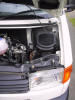
The original vehicle looked like this before the job commenced. [Picture]
This is a 2002 2.5tdi with the short bonnet and without ABS etc.
Operation A
For vehicles without ECU & Fuse box in front of battery proceed as follows…
A1. Ensure that you have the Radio reset code if required!
A2. Remove the battery cover, side cover, fresh air input duct and pollen filter if fitted.
A3. Disconnect both connections from the battery, -ve first.
A4. Remove the battery restraining clamp and lift out the battery. Now check that your battery will fit in the new position. If it has been replaced at some time by one that is more than 340mm long it will not fit between the headlight and the back of the bracket.
A5. Fit the new support plate into position and bolt it in with the bolt from the original battery clamp.
A6. The large +ve cable to the starter should reach to the new position for Main battery along with any extra wires that serve the rest of the original wiring. These will depend on the specification of your base vehicle.
It is vital that any wires that are moved are protected from chaffing on any part of the vehicle. Errors of judgement here are likely to result in a FIRE.
A7. Next revise the earth (-ve) connections to reach the -ve terminals of each battery with cables long enough to remain slack and without fouling any sharp edges. New ones can be purchased from most motor accessory stores. Remember -ve ones are a different size to +ve ones so buy the correct ones. The vehicle earthing bolt to which these connect is rather awkwardly placed below the fixed plastic lower battery cover. The original cable may continue through to the gearbox, if so it should be cut to remove the battery connection and new ones fitted of sufficient length to reach each battery. Maintaining the correct size and connection quality of these cables is essential as they carry ALL the vehicle current including starting current. Believe me it’s a lot and poor connections here will get very hot, again a fire hazard.
There are additional earth (-ve) cables, brown in colour, to reconnect to the main battery –ve terminal, these will vary depending on the specification of your base vehicle. Should any of these need extending remember to use good quality crimp up connectors and cable of a matching thickness to the original.A8. It should now be possible to fit both Auxiliary and Main batteries and clamp them tightly into place. It is a requirement that vehicle batteries are securely fitted so don’t miss the clamping procedure.
A9. The Auxiliary battery still has only one (-ve) connection so all that now remains is to connect the ‘Split Charge’ relay, its cables and the cable(s) to the Domestic wiring of your camper. For details of this see a later section.
A10 Re-connecting the main battery. Double check all of your connections for correct location and tightness leaving the -VE terminal until last if you are happy with your work ensure all services of the vehicle are switched off and replace the -ve connection to the battery. If there are any serious sparks here disconnect immediately and check again.
Operation B
For vehicles with an ECU & Fuse box in front of battery proceed as follows…
Follow above instructions A1 - A4 inclusive then ….
B1. Remove the fuse box upwards from its bracket by sliding a narrow screwdriver down the slot in the centre of the rear to release the clip. Disconnect and separate the red cabled +ve connections from the main +ve battery connector.
B2. Cut the fuse box support pillar from the battery clamp plate. [Picture]
B3. Clean up the cut edges and drill to take two large self tapping screws. (I used ones with 10mm hexagon heads like those that are used to fit the front wings to the body along their top edges.) Paint the cut and drilled surfaces to prevent rusting.
B4. Mount the modified bracket above the large grometted hole in the bulkhead using the screws as indicated above. Location as shown [Picture] with fuse box fitted. Check under the dash to ensure that there is nothing to damage with the drill and screws.
B5. It is necessary to extend the feed cable that runs between the Main Battery +ve terminal and the top right of the fuse box. To do this it is necessary to dismantle the fuse box. Start by removing any other cables that connect to the box, marking them to ensure correct replacement.
B6. With the fuse box detached from the vehicle and at the workbench unclip the rear mounting plastic plate then unclip the rear cover by carefully prising the sides out of their retaining clips with a small screwdriver. With this cover removed the connector to the short thick red wire can be removed.
B7. This short red wire needs to be replaced by one of almost 1metre long and fitted with connectors like the originals. I was able to open the originals and re-use them, I don't really like the practice but as they are somewhat non standard it was the easiest solution. Having industrial crimping pliers to hand the crimps were remade well but to be on the safe side I also soldered the connectors to the wire. The fuse box end was also protected by heat shrink covering as it now resides rather close to the bodywork.
B8. The fuse box can now be re-assembled quite simply in the reverse order to disassembly noting the angle of the bolt head where the connector has been replaced as it fits into the plastic moulding.
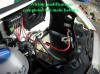
B9. The connector at the fuse box end needs to be bent backwards to clear the edge of the fresh air intake box, maybe best assessed as the box is replaced in its new position. Shown here with most of the wiring completed. [ Picture ]
B10. There will be some re-routing of cables to make them reach the new location. You may be lucky and not need to extend any other +ve wires but if you do, remember to use good quality connectors and wire to match the thickness of the original. It is vital that any wires that are moved are protected from chaffing on any part of the vehicle. Errors of judgement here are likely to result in a FIRE.
B11. There will probably be at least one -ve cable to extend to reach the eventual new position of the main battery -ve terminal but this is best left until the ECU is moved as it is difficult to asses the required length.
Operation C
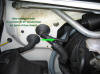
Shifting the ECU out of the way. Remember this item is VERY EXPENSIVE so damaging it WILL damage your bank balance. The job is quite easy using the original mounting frame modified and fitted to the lower battery support with a piece of angled aluminium. This operation can be done before moving the fuse box if necessary. If this is the case there are no wiring modifications to carry out, it's all metalwork mods. Do it like this…
C1. Remove the ECU from its mounting frame by releasing the side clips and sliding the unit upwards. There is no need to disconnect any of the wiring from the box.
C2. Remove the mounting frame from the vehicle by unscrewing the 8mm headed screw from the top 'leg' and prising the frame from its other three supporting pegs.
C3. At the workbench cut the frame as shown in the photo. Flatten the shaping A, drill holes for 6mm bolts at B, clean up the edges and paint to prevent rusting. (If only I could find the photos I would include them!)
C4. Cut a piece of 30mm aluminium angle to the length between the strengthening mouldings of the battery support just below the battery clamp. (DIY shops usually have this, it's very useful stuff to have about so don't shy away from buying a length) You can use steel but then it has to be cleaned up and painted so I find the aluminium easier.
C5. Drill one face of the angle bracket to fit the holes that were made in the modified ECU mounting frame and fit the two parts together with 6mm nuts and bolts. Self locking nuts may be a good idea.
C6.
Take the angle bracket to the vehicle and line it up horizontally below
the battery clamp, I found a hole already existed on the outer edge so utilised
this as one mounting point and marked to drill both the aluminium for both and
the battery support for the inner one. The height is determined by the downward
protruding leg which can be bent to avoid the fuel filter and provide extra
support. I used this to force the bracket upwards at the front to give some
slope to the unit to prevent water lying on its top surface.
How the **** did you get access to there I hear you ask.
Well it's easier with the headlight out!
C7. Headlight removal. Three screws out of the top of the plastic radiator grill, two screws out of the lower radiator grill. Plastic tool from the vehicle toolkit on the jack is used to pull out the whole lower front panel. Use the hooked end of the tool worked in to locate the inner lip of the metalwork at each outer corner in turn to pull the panel off its retaining pins. (They are similar to those that held the ECU plate to the body.) Now the front is opened up the lower headlight fixing screws are visible so the whole unit can be removed after disconnecting wires from bulbs and electric adjusters if you have them. It is easier if the flashing indicator is removed first, this is attached to the side of the headlight with a plastic clip releasable with a small screwdriver.
C8. The hole mentioned at C6 above can be drilled with a short length electric drill, my Bosch battery drill did the job with a bit of a struggle.
C9. It should now be possible to fit the modified ECU mounting frame and its angle bracket to the vehicle with 6mm nuts and bolts, self locking may again be a good idea although access to them is not too easy.
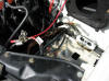
C10. The ECU will now re-fit to the mounting frame in an almost horizontal position thus leaving room for the new battery tray. [ Picture ]
C11. In preparation to turn the battery there is a Brown -ve wire to extend to reach the new position of the -ve terminal of the main battery. Do this as indicated before with good quality crimp connectors and cable of the same thickness.
With both the fuse box and the ECU re-sited the new battery plate should fit into position and work can proceed at A5 above. Doubtless there will be differences between individual vehicles, neither of my three have been the same but the above procedures will help overcome most eventualities.
Pictures of various parts of the installation, click to enlarge.
 Mounting Plate in place without any auxiliary battery wiring.
 As above just from a different angle.
 Main battery fitted, connected and clamped with dummy base for auxiliary
battery.
Main battery fitted, connected and clamped with dummy base for auxiliary
battery.
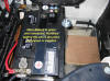
 Wiring and relays installed for auxiliary battery.
 Wire protected in tube to connect split charge and fridge relay control to fuse
box.
Wire protected in tube to connect split charge and fridge relay control to fuse
box.